
By Paul Grana, co-founder, Folsom Labs
In earlier articles we’ve already pointed out that inverter clipping isn’t as significant as most people think, and that in a grid-power-constrained system it may be economically optimal to have a rather large DC-to-AC ratio. But what if there was a situation that resulted in significantly higher (and unexpected) inverter clipping losses of 30% or more? We’ll show you how to understand and avoid these cases of inverter “hyper-clipping.”
What really happens when inverters clip power?
It’s easy to say that the inverter “clips the excess power,” but from a physics point of view, that doesn’t describe what is going on. You can’t just “throw away” power you don’t want—and inverters don’t have air conditioners they can turn on when they need somewhere to send the excess energy. The main tool an inverter has is setting its DC voltage—and this is actually how an inverter is able to drop the system power.
It helps to visualize this issue graphically. A solar array has a power-voltage curve that illustrates the relationship between the operating voltage and the array’s output power. The modules can perform anywhere on the curve, and it’s the inverter’s job to pick the spot on the curve—ideally at the spot that maximizes the power (called the max power point, or MPP).
Figure 1: Typical array power-voltage curve
At the same time, an inverter has a maximum operating power and a voltage range it operates within. We can visualize the inverter’s operating range as a rectangle.
Figure 2: Array power-voltage curve in over-power clipping
When an inverter is in an over-power clipping mode, the array is producing more power than the inverter can handle. The inverter will increase the DC operating voltage, pulling the modules off of their max power point, until the modules’ DC power is within the inverter’s operating range. You can see this as the green point in Figure 2. The inverter protects itself while maintaining maximum power production. The modules end up dissipating the excess power as heat, but as we’ll show at the end of the article, this isn’t a big deal.
However, there is a scenario where this behavior can cause problems. Specifically, look at what happens if the arrays’ power-voltage curve doesn’t intersect the inverter’s operating range. The process we described above (the inverter increasing the operating voltage until the modules’ DC power is within the inverter’s operating range) doesn’t work. Instead, the array will miss the inverter voltage window and trip off—for that period of time, the energy production will be zero. Note that this is by definition happening at a time when the array is at peak production—so just a few times a year can have a serious impact on the array’s energy production!
Figure 3: Array power-voltage curve in over-power and over-voltage condition
So how might this come up?
The description above is a theoretical framework, but how might this issue come up in an actual system?
There are a few ingredients needed to make this happen: a location with lots of sun (high power) combined with relatively cold temperatures (high voltages), high designed string voltage relative to the inverter’s max operating voltage and a large DC-to-AC ratio.
We can look at the power and temperature properties for a few locations around the US, and it looks like there are a few cities that are at elevated risk for this (again, high irradiance relative to temperature). We’ll use Los Angeles for the analysis here.
Figure 4: Sunlight and temperature by location
We then design a system in Los Angeles with an inverter with a max MPP voltage of 750 V (combined with a 1000 V Voc string), and 1.5 DC/AC ratio.
Figure 5: Loss chart for hyper-clipping simulation
We can see that the clipping losses can be as high as 32%, caused by 15% of operating hours where the array goes into hyper-clipping and trips to zero.
In terms of seasonality, these clipping losses persist for most of the year, with clipping losses above 30% for seven months of the year.
Figure 6: Clipping losses by month
Sensitivity to design choices
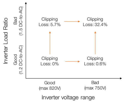
It’s worth illustrating how these two factors interact. Note that if we start with a base case of an array with a 1.2 DC-to-AC ratio and an inverter with a wider max voltage of 820 V, then there is no clipping loss. Each factor independently will lead to clipping of 5.7% (for increasing the DC/AC ratio to 1.5), and 0.6% (for dropping the inverter’s voltage to 750 V. But together, the clipping losses jump to 32.4%—approximately five times the sum of the individual effects.
The good news is that HelioScope will properly simulate these losses—so if you are ever at risk of hitting these conditions, you’ll find out before you build the array. And it’s a reminder that inverters aren’t just black boxes that turn DC power into AC power. The nuances of their behavior (including the operating voltage range) can make a big impact on energy yield.
How much heat does this create at the module?
This description of clipping often raises questions about the module health. Basically, if the inverter isn’t ‘clipping’ excess power but the modules are, then does this damage the module?
To re-state the process described above: During inverter clipping, the modules are working off of their maximum power point. So at a moment when a module wants to produce, say, 320 W, it is only able to deliver 240 W to the inverter. The difference (in the example, 80 W) results in heat at the module. So, how much heat are we talking about?
Here, it helps to think in terms of thermodynamics. Modules are only about 20% efficient at converting sunlight into energy—and the rest, 80%, is largely dissipated as heat. So, say an inverter is clipping 25% of the array’s production (as in the example above). Then in the broader context of the sunlight, the 20% efficient module is only converting 15% of the sunlight’s energy to power, with the resulting energy, 85% of the sunlight, being converted to heat. Compared to the base case (80% of sun’s energy converted to heat) this is an increase of ~6%. Sure, any extra heat isn’t ideal—but any well-made module should have no problem handling that extra heat.


Hi, I am working with a homeowner on a project in Pennsylvania. The utility company conditionally approved our interconnection application. In order to install they said we must: PECO has sent back viable solutions for this account. Please see options below.
1) All inverters within system to adopt an overvoltage (OV1) setting of 253 (on a 240V base) and a clearing time of 60s or 3,600 cycles. This option requires completion of an Inverter Addendum which supplements the PECO Interconnection Agreement.
The system is currently designed as a 11.36 kw dc system projected to generate 12,148 kwh per year. Does anyone know how this setting will affect the homeowners solar production?
I received the same feedback from PECO. My system is exactly the same as your size as well. Did you get an answer to your question? What path did you take and any feedback is very much appreciated.
Get the software for the inverter and limit its max output to 80% or even 75% of rated otherwise lifespan will be shortened. . . . . 80% and it’ll go for many years
Fit as many matched panel strings as ye wish well below the inverter VOC max well within the inverter MPPT range. . .
I use an isolating diode on each string positive . . . .Whether that is really neccesary or not I dont know but my set up works and has been going for some years
Once the inverter reaches its max power the inverter will simply allow the dc volts to float resulting in lower amps . . . .Amps being the big wear and tear on the components.. . .
The panels will be fine
Solar pv can be open circuit with no harm
When PV panels are used on stand alone whether it be older pwm only or later mppt chrage controllers which also uses pwm to limit input the pv panels in effect go gradually to open circuit. . . . .Hope that helps a bit
When VMPP range of panel string (series connection) maintain +/- 2% of VOC range of Invertor/PCU/MPPT, you will never face Clipping/ Surge problems.
I have a 18.81 kWh system with 2 SolarEdge hd 7600 inverters on 2 strings , I am considering in adding a hd 1000 SolarEdge inverter and having 3 strings 15,15.and 24 on the 1000 to stop clipping for maximum production with a 25 kWh inverter. Am l making the correct decision?
Very interesting article. We have a 4kw invertor which claims to operate at 96.5% efficiency. A supplier said they could increase the export of electricity to the grid by 40%.
Given what I have read above I assume they will install another devise next to the power supply to reduce the clipping and improve the export of electricity.
Still unsure.
Hi,
Is this hyper-clipping technique by going to a higher operating voltage-instead of MPP voltage- is the same used by an off-grid inverter whenever solar production is exceeding the (load + battery charging) demand ?
I noticed a similar energy loss phenomenon in one of our projects in Zambia and I am trying to figure out why it happens :
We are using an off-grid inverter/charger with MPPT window (60-115 Vdc). We are using Module configuration of
3 panels in series x 4 strings in parallel
Module is 335Wp- 45.98Voc – 37.26 Vmpp @STC
Temperature coefiicent of Voc is -0.311%/°C
Providing that minimum ambient temperature in Zambia does not go below 18°C, it was strange to observe on the inverter’s monitoring system that PV input voltage reaches 120V (exceeding the 115V MPPT window) ! and more surprisnlgy this happens – not in early hours of the day when low temperature effect can be greater – but starting from 10:00 am and until 3:00 pm.
Can this operation at higher voltage is done by the inverter to just clip excess power and match the needed power demand of battery charging + load ?
Any other explanation ?
Kindly advise and how to avoid such losses
One thing to keep in mind, and I have run into this in the real world, is the inverter models supplied by the manufacturers that are input for PV system analysis software are not always accurate. I remember one particular case where an inverter manufacturer limited the MPPT voltage limits in the specifications to increase the inverter’s efficiency in some tests but the MPPT range was actually much wider. The limited MPPT voltage window was in the inverter model so when I modeled the inverter it showed it shutting down when it actually would not have. The inverter manufacturer confirmed that the MPPT tracking window was wider than the module but that did not help in when I was trying to do an energy production estimate for the client. The only way around this was to make a custom inverter model file.
Thank you for your article – even though I do not totally understand it. What I do understand, however, is that we will not be getting the full benefit the sun could provide – and that depends on… various issues..
We are in the San Francisco Bay area and about to invest a large amount (for our budget) on going all electric – all solar on a 3-bdrm/2-bath home. We are firm believers in doing everything we can possibly do for our environment but are not ‘fanatics’: We also believe in being reasonable and prudent. So what do we have to look for regarding inverters, etc. as per the article? How can we be sure we are getting the maximum possible return on our investment when it comes to optimizing the power output?
Also, the current proposal uses Solar World panels: We like the ‘Made in USA’ issue, but how stable is the new Oregon company and how reliable are the panels? Is there a website that compare different systems (equipment) to help verify dependability, output, life expectancy, etc.?
Thank you so much.
Instructive article.
So the modules should be able to handle the extra heat.
I was wondering what risks there are to the inverter when the modules produce more then it can handle.
Our modules are 50% oversized. On most days they will stay within the inverter’s box of parameters. But occasionally there will be the very sunny day.
TX
-L
Really great article. So little thought sometimes given to inverter design parameters and the implications of even slightly moving outside of them. Good read even for a resi/ small comm installer like me.
Wonderful analysis..thank you so much ..I think the problem of the solar array still the low efficiency of the solar modules…I hope the research in Nano-Technology will lead to a structure able to produce much power than the conventional method we have today..
Inverters are cheap when compared to panels, mounts, and real estate. I don’t recommend clipping at all.
Also I expect a slightly oversized inverter to live longer.
@Ian Nelson this is no longer true. Panels are now cheaper than inverters. This is also a reason why dual tilt arrays are becoming popular.
Clipping is necessary to get max production.