
Image credit: SEI
The National Electrical Code (NEC) requires bonding electrically conductive materials and equipment to establish an effective ground-fault current path.
In general, bonding a piece of equipment means connecting it to an equipment grounding conductor (EGC) that is bonded to the overall grounding electrode system. The goal is to take all of the metal in a system that could become energized during a fault (besides the current-carrying conductors) and connect them together so they are effectively one piece of metal. That “one” piece of metal is then connected, by EGCs, back to the source of power, completing a circuit for any fault current. Bonding prevents a host of possible risks and dangers.
“Imagine: the insulation on a PV source circuit wire becomes damaged, and the current-carrying part of the conductor makes contact with a frame or rail,” said Brian Mehalic, PV Curriculum Developer and Instructor at Solar Energy International. “Now that metal, which is not normally part of the circuit, has potential voltage relative to whichever pole in the DC circuit is not faulted, and may even be carrying current during system operation. This is a dangerous situation, because there is now the possibility of a fire, as well as a shock hazard.”
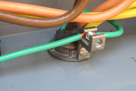
Image credit: SEI
Regardless of system voltage, equipment grounding is required on all PV systems. Appropriate bonding and equipment grounding limits the voltage imposed on a system by lightning, line surges and unintentional contact with higher-voltage lines. It also limits the voltage-to-ground that can occur on normally non-current-carrying metal components, ranging from frames and rails to conduit and enclosures.
“Bonding and grounding PV systems ensures public safety, as well as the safety of PV installers and field electricians,” said Andy Zwit, Codes and Standards Manager at ILSCO.
Excluding modules, the majority of components in PV systems are bonded like any other electrical system. For example, grounding busbars are connected to the metal chassis of enclosures, such as disconnect switches, combiner boxes and inverters, and then an equipment grounding conductor (EGC) is connected to the busbar, Mehalic explained.
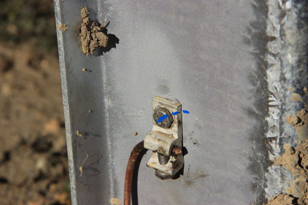
Image credit: SEI
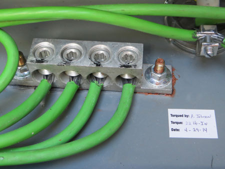
Using approved mechanical connectors and bonding washers are two popular bonding and grounding methods. Mechanical connectors can be mounted to a module or racking frame with lay-in features which accept a copper wire that bonds and grounds components, said Zwit. Bonding washers are used in conjunction with hold-down clamps and bolted joints on the racking system. The washer fits over the bolt, and when tightened to the prescribed torque value, pierces through oxidized or coated surfaces, providing a solid bond between metal parts.
A number of factors make the grounding and bonding of a PV system difficult. PV systems are exposed to the elements, which can result in atypical situations where the usual practices for bonding may not perform as intended. For example, many listed grounding lugs are not designed to be installed outdoors; using a lug that is not rated for outdoor use can lead to premature failures in the intended path for fault current, hampering the functionality of overcurrent and ground-fault protection devices, said Mehalic.
Expansion and contraction from thermal cycling, as well as different expansion rates for different materials – such as steel, aluminum, copper and PVC – can result in loose connections over time, even when the equipment was initially installed properly, Mehalic explained. Proper installation isn’t a given, though. The anodized coating on module frames and racks requires appropriate connections and hardware to penetrate the anodization, also preventing corrosion where the bare aluminum has been exposed.
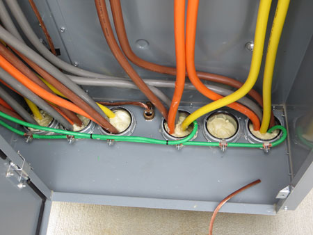
Image credit: SEI
Additional difficulty in grounding PV systems results from the interactions of dissimilar metals used for racking structures, module frames and grounding devices, he added. When combined with moisture, these interactions can lead to corrosion and failure.
How do you know if a system has been properly bonded? From a manufacturer’s point of view, the testing done to comply with UL and CSA standards ensures products meet requirements for safety, repeatability and longevity, said Zwit.
“In the field, an installer should follow the manufacturer’s installation instructions for PV system components and the guidelines set forth in the NFPA-70 NEC Handbook, as well any requirement dictated by the local AHJ,” he said. “Following installation, but before energizing a system, there are several methods that can be used to test and ensure a system is properly bonded and grounded.”
“System grounding, as well as equipment bonding and grounding, must be addressed in detail during the design phase, with equipment and connection methods clearly stated,” said Mehalic. “Without a proper understanding of the intended design, the installer’s job is much more difficult. Special attention must be paid to the types of connections that are unique to PV systems – such as module-to-rack bonding, outdoor use of lugs and dissimilar metals in close proximity.”


My solar inverter has a ground fault interruptor built in to it, When I connect to the grid which includes my home service, do I need to remove my bonding screw at the meter?
Why would you need to remove your meter bonding screw?
I am very confused about this requirement to connect the PV frames to ECG. I understand the ECG would only carry current in a fault condition and would cause enough current to flow back to the source (AC Panel Neutral) to blow the breaker making the system “safe” again.
I don’t see how this plays out with the DC power that faults to the ECG – All that would do tie the DC line to earth and the neutral back in the panel and the bound earth ground – in no way does it create a scenario that would cause a fuse or breaker to blow in the PV Combiner box. The ECG would not clear the fault. (Consider as well that the PV panel is self limiting as far as excess current goes – Asc).
I would really like to understand why tying the frame to ECG would make this safer.
I could see a reason to connect to earth ground to help blead off any induced current from a near by lightning strike or something)
The PV inverter would detect the ground fault caused by the affected module (hopefully) and then it would trip off. Once the inverter stops producing power, the current stops flowing, an error is flagged, and the installer can then start troublehooting.
It shuts of inverter ac output but not eliminate the dc side that is grounded.
I have a Zamp Solar 140 two panel solar. I have got the importance of Grounding but not using a Bonding wire and the purpose of it. In camp I have two12V exhaust fans for the toilets (male and female). and two 12V Dayton DC Axial fans. Beside this my concern is for the 140 equipment. At present I am just getting started. I did look at G ranger’s bonding wires which are many as are the prices. Being a PV two panel I was interested in getting a bonding wire and learning ways in which it can be used. You will like this I am sure. The way you turn the 140 off and on is a “blanket”
and how to ground the minus wire in amorphous modules to prevent corrosion of the TCO?
Question:
We have an existing LPS on a roof. And we’ve installed pv inverters on roof. Are we allowed to equipotential bonding the inverter cover PE terminal with existing Wires or buses which are Lighning strike route wires? Thank You
Question. I saw an old G electrician scolding a new guy because he grounded the rails on one side of the racking and at the jbox he just added a ground lock and a foot of copper to connect with the ground wire coming from the inverter is it wrong does copper wire grounding has to be continuous???
Which type of conductor should we use for PV module frame earthing? Bare conductor or insulated conductor?please answer according to reputable standard like NEC,IEC or etc.
What does your AHJ say? Most people use a bare copper wire that is strong enough to handle any situation it may be in. Although a insulated ground has been used before. Although more expensive possibly and the insulation if not rated for sunlight and water will degrade quickly.
This was good info, but where do l find labeled pics of connecting pcs to do grounded DIY from solar array to charge controller to inverter to battery bank—and where to connect to on the devices? I want to do an exterior standalone, earthground at battery-negative to run outbuilding lights, fence charger, and carpentry tools. Thank you.