By Terence Parker, Application Engineer, Ginlong Solis
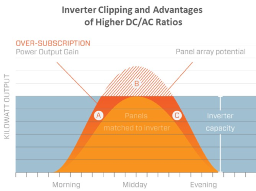
Inverter clipping, or “inverter saturation,” occurs when DC power from a PV array exceeds an inverter’s maximum input rating. The inverter may adjust the DC voltage to reduce input power, increasing voltage and reducing DC current. Alternatively, the inverter may restrict or throttle the inverter’s AC output. Inverter clipping is typically seen in PV systems that have high — for example, greater than 1.4:1 — DC/AC ratios.
Why does it matter?
Contractors — more specifically, system designers — across all segments of the solar industry will at some point evaluate the impact of inverter clipping on their system’s generation capacity and performance. Changing the DC/AC ratio is a powerful tool for optimizing the system’s levelized cost of energy (LCOE) for long-term owners, or for increasing PV system internal rates of return (IRR) for investors or developers.
Fair warning: Not all inverters can accept higher DC/AC ratios!
If the inverter clips output power on the AC side, field experience shows that internal AC components will wear out faster. But overloading the DC side of these inverters may void the warranty, so installers must check for a maximum DC/AC ratio on the manufacturer’s datasheet.
Alternatively, there are new inverters that reduce the DC input power — and therefore AC output power — without stressing internal components. Advanced string and central inverters will self-limit to protect internal components, but it is critical that the designer keep the array input voltage below the inverter’s maximum limit. Additionally, the maximum short circuit current of the system must not exceed the inverter’s rating, or the maximum power rating of its DC components such as terminals, busbars and MPPTs.
When a PV system is designed to clip
A contractor can determine what project size a new site can accommodate, but residential systems may be limited to a 40-amp breaker by the home’s main service panel. A larger, more expensive breaker panel would be needed to accommodate more solar. So even though a PV system designer may be able to fit a 10 kW PV system on the site, a homeowner may decide to limit the inverter size to 7.6 kW — typically landed on a 40 DPST breaker — to reduce costs or to better match the site’s loads.
Commercial building owners may find themselves in a similar situation if, for instance, their warehouse roof could accommodate 2 MW of PV, but their local utility connection only accepts a maximum of 1 MW of distributed generation power injection to the grid.
So why would a homeowner or a commercial building owner encourage their solar designer to create a system that would clip PV array power from 3% to more than 10%? In short, it’s about the money. The system owner wants to generate a higher IRR and increase the net present value (NPV) of cash flows.
This chart shows potential energy losses as the PV system DC/AC ratio is increased from 1.1:1 to 1.8:1.
Residential and commercial systems optimize DC/AC ratios for different reasons
It is rare that a homeowner will look to maximize a PV system’s short-term income in exchange for long-term value. Generally, residential owners are in it for the long haul — at least seven years in the home or over a 15-year mortgage. Residential customers are more likely to look for a system with the lowest LCOE. For a technology like PV with zero fuel costs and limited O&M expenses, LCOE changes most dramatically in proportion to the system’s initial capital outlay.
As utility rates continue to rise, residential buyers want a low-cost system designed for longevity and optimized for energy density that produces reliable kilowatt hours. On sunny days, the PV system might clip output by 1% or 2%, but very little energy is wasted when it’s designed with a 1.2:1 to 1.3:1 DC/AC ratio.
On the other hand, commercial PV system buyers or investors may want a high performing asset that optimizes power density. Such a system may have a 1.4:1 to 1.7:1 DC/AC ratio. While the local utility may limit the system to a 1 MW inverter, the commercial building owner may want to use more roof space to increase the DC/AC ratio to boost IRR and cash flow NPV.
Managing clipping loss in utility-scale systems to maximize profits
This strategy is also used in large industrial and utility-scale ground mount systems to maximize profits during the first five years, when both the ITC and the 5-year depreciation revenues are realized. These asset owners will design their systems to optimize IRR and NPV of cash flows accordingly. Investors burdened by fixed costs — including permits, insurance, wire, racking and fixed O&M costs — want to get money back as quickly as possible. A high DC/AC ratio to maximize AC kilowatt-hour output helps to meet that goal.
Balancing inverter clipping ratios to tune cash flows
Pushing the limits of DC loading on an inverter could be detrimental to its long-term service life. But new inverters are designed to handle high-power systems; commercial owners and developers look less at clipping loss percentages and more at total energy generation from the site. Installing more modules does not increase the installation cost per panel. So the designer can add more panels, increasing the DC/AC ratio, until costs balance against expected added revenue, as reflected in the graph below.
As the contractor adds more modules to a fixed power inverter, mid-day production on high irradiance days will max out the inverter’s AC output rating, with extra production coming in the mornings and afternoons. If there are advantageous time-of-use electricity rates in the late afternoon, designers may adjust the azimuth of the array as another strategy to optimize kilowatt hour production late in the day, increasing the system’s IRR.
This graph illustrates how a PV system with a higher DC/AC ratio (e.g. 1.5:1) will produce more AC power and more revenue in the early mornings and late evenings, compared to a PV system with typical DC/AC ratio of 1.2:1.
Inverter manufacturer DC/AC ratio limits are meant to ensure that AC components remain within their tolerances if the designer overloads the inverter on the DC side. But many new inverters — such as those in the Solis Residential Single-Phase portfolio with models ranging from 2.5 kW to 10 kW — reduce AC output by adjusting DC voltage and current. Solis has built-in self-protect features to guarantee the long-term safety and performance of internal components. Solis also has one of the widest voltage range on the market (90 to 520V), and dynamic, independent maximum power point trackers (MPPT) resulting in higher generation during low irradiance conditions in the early morning or late afternoon.
If the central or string inverter is the type that “clips” PV power on the DC side to protect against overloading, solar designers have a wide range of options they can offer. Installers should take advantage of inverter clipping to accomplish the different goals of solar installations from residential rooftops to utility-scale solar farms.
 With a career in renewable energies spanning almost 30 years, Terence Parker has seen the solar industry expand from small PV lighting systems in remote locations to multi-megawatt urban PV sites connected directly to the utility grid. Parker began his career in 1990, in the Marshall Islands where he worked as a marine biologist, an overseas PV project manager and a PV system trainer in the Marshalls, other Central Pacific countries and many other remote sites around the world. Moving back to the U.S. in 1999, Parker joined United Solar where he developed thin-film PV products and PV roofing systems. In 2010, he began his work with microinverters and PV string inverter manufacturing, application engineering for SolarBridge before joining Ginlong Solis USA.




Hi Terence! Do you have an explanation, why inverter manufacturers indicate very conservative clipping ratios (say 20%) if there seems to be not really a good reason for it according to your blogpost?
If I understand you correctly, the indication of max installed DC-Power for an inverter is not really relevant, as long as the max. voltage and current is respected? As the MPPT anyways would look for a working point in the “safe” range of the inverter without blowing itself up (say it starts at 0V then increases voltage until it hits the max rated power of the inverter, even if this is only halfway along the power-curve)? If I take this to extremes and I connect 2kW panels (1kW east, 1kW west) to a really small inverter like 500W, it could still work, as long as the maximum string voltage is respected?
Regards
Baelis
clipping is done by rising the DC capacitor voltage , manufacturers who chose a lower capacitor voltage ( cheap) can not do this or limited , SMA can do 200% (P^/Pac)
east west will do 0.6 (1/0.6) expect no clipping , but you will need 2Mppt
When using a 50KW inverter
Is it possible to set the output AC voltahe to a higher lever than 400V to make provision for volt drop when using long LV cables
some inverters can do , modify the standard grid parameters , the grid connection point on the meter is the measured voltage of the grid operator , it will generate a event log if feeding back in the voltage is to high , better reduce the voltage with the Q/U , and P/U curve settings , the number of hour its needed is realy limited , an prevent tripping of the inverter ( 50% is always better as nothing , by preventing tripping) , and will prevent damage to your inverter by flipping on and of and on….)
Your final image indicates an example of A+C>B. However, it’s for a single day. I imagine the formula holding true if the daylight hours did not change throughout the year. Would you agree?
With the earth tilting (change of hours), and cloud coverage occurring randomly, the azimuth of the array, the array facing the morning or the evening, tree coverage, would all have effect on that formula holding true, correct?
Considering most people that go solar need to have a roof that sees the sun from Google imagery usually the midday hours are the most beneficial. If your inverter allows that type of clipping A+C would never be greater than B.
I’m not saying I’m right….I’m looking for an experienced explanation….Thanks!
“It is rare that a homeowner will look to maximize a PV system’s short-term income in exchange for long-term value. Generally, residential owners are in it for the long haul — at least seven years in the home or over a 15-year mortgage. Residential customers are more likely to look for a system with the lowest LCOE. For a technology like PV with zero fuel costs and limited O&M expenses, LCOE changes most dramatically in proportion to the system’s initial capital outlay.”
Personally in the hot south western States, I would go with an inverter that would be slightly over rated for the array’s output. Power curtailment at the typical 104 degrees F can actually lose power needed during those hot days and almost continuous air conditioning running. I have also found that over the years, that VFDs although they are actually motor controllers, when just “right” rated sometimes will trip out during extreme ambient heat. At that time is when one wants to over rate the VFD to the motor, as in 30 H.P. on a 25 H.P. motor. The VFDs perform better, last longer and can take abuse better.